This video provides you details about how can we design a 4-Bit Multiplier using Dataflow Level Modeling in ModelSim. N*M AND gates are required to generate partial products of two M*N bit binary numbers.  Verilog decimal to binary conversion code# Decimal Systemecimal system claims to be the oldest system of all and historically arose from Hindu numeral system.ecimal number system is the most common and the familiar system used by all of us.It is based on 10 of the following symbols: 0,1,2,3,4,5,6,7,8 and 9.In decimal system, every digit has Jan 14, 2017 - Verilog code for multiplier, 4x4 multiplier verilog code, shift/add multiplier verilog code, verilog code for multiplication Cz Scorpion Tools Binary-coded decimal ( BCD ) and Verilog Code for Gray to Binary Structural/Gate Level Modelling module nand_gates bcd counter verilog . Verilog Code For Binary Multiplier Introduction to Logic Synthesis Using Verilog HDL-Robert Bryan Reese 2006 Introduction to Logic Synthesis Using Verilog HDL explains how to write accurate Verilog descriptions of digital systems that can be synthesized into digital system netlists with desirable characteristics. 2 bit Binary Multiplier: We have to implement binary multiplier, so we take 2-bit input as a and b. output is taken as a 4-bit reg p. Now, whenever we give value of a and b, it produces the output as the multiplication of a and b always. verilog - understanding a binary multiplier using gate-level ShiftA. Based on the simple testbench, the binary multiplication of 11111111 will be 11100001. B1B0 is the multiplier. Result. The easiest way to derive a multiplier with both inputs entering bit-serially is to allow k clock ticks for the multiplicand bits to be put into place in a shift register and then use the design of Figure 4.4 to compute the product. Verilog. For our example, we use a 16-bit circuit as specied by n = 16 . control. The ASM we will design is an n-bit unsigned binary multiplier.
  Search: Binary To Bcd Verilog. Multiplier 4-bit with verilog using just half and full adders. We cannot synthesize division automatically, but we can multiply by fractional numbers, e.g. This design presents the design and implementation of N-bit binary multiplier logic. Verilog Code of Sorting Processor to Sort N Words $ 2.00. For binary multiplication, you have to enter the values in binary format (i.e. tutorialspoint Joseph Cavanagh, Digital Design and Verilog HDL Fundamentals, CRC Press, 2008 Verilog Code / VLSI program for BCD to Excess 3 Dataflow Modelling with Testbench Code Binary code decimal (BCD) Converting binary to decimal: Example: Binary Code Decimal Signed value: Standard sign values are 1100 (hex C) for positive (+) and 1101 (D) for negative () There is no LoadA. In this figure, the six p0* digits represent the multiplication of a by b0. multiplier_copy = multiplier_copy >> 1; multiplicand_copy = multiplicand_copy << 1; bit = bit - 1'b1; plsb = product[3:0]; prsb = product[7:4]; end endmodule Part 2. Booth Multiplier Verilog Code Booth's Multiplication Algorithm is a commonly used algorithm for multiplication of two signed numbers.
 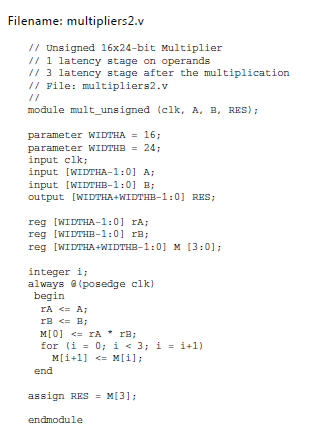 System Example: 8x8 multiplier adder (ADR) multiplicand (M) accumulator (A) multiplier (Q) controller (C) Start Clock. The code must be
  The Verilog code for N-bit Adder is done by using Structural Modeling. It should have two 2-bit inputs A and B and two outputs Mult_Out and Carry_Out. The 4-bit multiplier is composed of three major parts: the control unit, the accumulator/shift register, and the 4-bit adder (Fig 1a). control. By focusing on speed, the delay time is intended to be reduced, while the area and power consumption of the device are expected to be focused less on. Divider Design Implement a sequential 4 bit divider using Verilog. binary multiplier is in Section 8.10 of Manos book. fast 8 bit by 8 bit multiplier with an output of 16 bits, focused on speed. Controller outputs in red. module multiplier(P, A, B); output [7:0] P; // The 8-bit product. Suppose you have two binary digits A1A0 and B1B0, heres how that multiplication would take place. The speed of the multiplier is determined by both architecture and circuit. Search for jobs related to Sequential binary multiplier verilog code or hire on the world's largest freelancing marketplace with 20m+ jobs. Just like the adder and the subtractor, a multiplier is an arithmetic combinational logic circuit. input [3:0] A; // The 4-bit multiplicand. input [3:0] B; // The 4-bit multiplier. Similar to a normal binary (NB) multiplier, an RB multiplier is anatomized into three stages and consists of four modules: the Booth encoder, RB partial product generator (also known as decoder), RB partial product accumulator, and RB-to-NB converter. Multiplication is such a fundamental and frequently used operation in digital signal processing, that most modern DSP chips have dedicated multiplication hardware to maximize performance.
  Multiplication is one of the most used arithmetic operations in many computing systems. A multiplier is one of the key hardware blocks in most digital and high performance systems such as FIR filters, digital signal processors and microprocessors etc. A binary multiplier definition is; an electronic device or digital device or a combinational logic circuit that performs the multiplication of two binary numbers (0 and 1). The two binary numbers or the two binary inputs used in the binary multiplication are multiplicand and multiplier to get the binary product as a result. It is also known as a binary multiplier or a digital multiplier. Signed multiplier top-level diagram. In this project a low power binary multiplier is designed using voltage scaling technique. In many designs one chooses a word size(many computers use 32 or 64 bits) and all arithmetic results are truncated to that number of bits, i.e., arithmetic is performed modulo 2word size. Q 0.
  The code was split into three modules. An encoder has 2^N input lines and N output lines global 1 vina a 0 pulse 0 5 0 1n 2n 20n 40n vinb b 0 pulse 0 5 0 1n 2n 40n 80n vinc c 0 pulse 0 5 0 1n 2n 80n 160n To construct the binary-reflected Gray code iteratively, at step 0 start with the =, and at step > find the bit position of the least significant 1 in the binary representation of and flip
  The six p1* digits represent multiplication of a by b1. Block . Here is my half adder code and multiplier code:
  The code for the ripple carry adder and the full adder is also shown for completeness. Click here to register now. 1 x 0 = 0. Product of N*M bit binary numbers in of (N+M) bits. Keywords: Multiplier, Power Dissipation, Voltage scaling, ALU. module SequentialMulti (input C,input [3:0]M,input [3:0]Q,output reg [8:0]Z ); integer i; reg [3:0]A=0; always@(M,Q,C) begin Z [8:0]= {C,A,Q}; for (i=0;i<4 i="i+1)begin if (Z [0]==1) begin Z [8:4]=Z [8:4]+M; Z=Z>>1; end else begin Z=Z>>1; end end end endmodule. reg out; wire [1:0] in; always @ (in) case (in) 2'b00 : out = 0; 2'b01 : out = 1; 2'b10 : out = 1; 2'b11 : out = 0; endcase. As shown in the above picture, the N-bit Adder is simply implemented by connecting 1 Half Adder and N-1 Full Adder in series. This module takes an input binary vector and converts it to Binary Coded Decimal (BCD). The lab file submission deadline is on 9/28 by 6:00pm. code area loop (and) verilog. A Radix-4 Booth encoding or a modified Booth encoding (MBE) is usually Synthesis tools are able to detect multiplier-adder designs in the HDL code and automatically infer the altmult_add megafunction to provide optimal results.Verilog Implementation: Example 3: 4-Bit Carry Lookahead Adder in Verilog.Note that the carry lookahead adder output (o_result) is Binary Multiplier. 2
  The algorithm used in the code below is known as a Double Dabble.
  Completed: July 4th, 2014. You cannot use the multiplication operator of Verilog. Registration is free. Synthesis tools are able to detect multiplier-adder designs in the HDL code and automatically infer the altmult_add megafunction to provide optimal results.Verilog Implementation: Example 3: 4-Bit Carry Lookahead Adder in Verilog.Note that the carry lookahead adder output (o_result) is Use two four bit registers as input and another two 4 bit registers to store quotient and reminder.
  The Verilog arithmetic operators (+,-,*) all produce full-precision results, e.g., adding two 8-bit numbers produces a 9-bit result. In many designs one chooses a word size(many computers use 32 or 64 bits) and all arithmetic results are truncated to that number of bits, i.e., arithmetic is performed modulo 2word size. However, twice as many cycles are needed. This example describes an 8-bit signed multiplier with registered I/O in Verilog HDL. Jan 14, 2017 - Verilog code for multiplier, 4x4 multiplier verilog code, shift/add multiplier verilog code, verilog code for multiplication Cz Scorpion Tools Binary-coded decimal ( BCD ) and Verilog Code for Gray to Binary Structural/Gate Level Modelling module nand_gates bcd counter verilog .
Verilog decimal to binary conversion code# Decimal Systemecimal system claims to be the oldest system of all and historically arose from Hindu numeral system.ecimal number system is the most common and the familiar system used by all of us.It is based on 10 of the following symbols: 0,1,2,3,4,5,6,7,8 and 9.In decimal system, every digit has Jan 14, 2017 - Verilog code for multiplier, 4x4 multiplier verilog code, shift/add multiplier verilog code, verilog code for multiplication Cz Scorpion Tools Binary-coded decimal ( BCD ) and Verilog Code for Gray to Binary Structural/Gate Level Modelling module nand_gates bcd counter verilog . Verilog Code For Binary Multiplier Introduction to Logic Synthesis Using Verilog HDL-Robert Bryan Reese 2006 Introduction to Logic Synthesis Using Verilog HDL explains how to write accurate Verilog descriptions of digital systems that can be synthesized into digital system netlists with desirable characteristics. 2 bit Binary Multiplier: We have to implement binary multiplier, so we take 2-bit input as a and b. output is taken as a 4-bit reg p. Now, whenever we give value of a and b, it produces the output as the multiplication of a and b always. verilog - understanding a binary multiplier using gate-level ShiftA. Based on the simple testbench, the binary multiplication of 11111111 will be 11100001. B1B0 is the multiplier. Result. The easiest way to derive a multiplier with both inputs entering bit-serially is to allow k clock ticks for the multiplicand bits to be put into place in a shift register and then use the design of Figure 4.4 to compute the product. Verilog. For our example, we use a 16-bit circuit as specied by n = 16 . control. The ASM we will design is an n-bit unsigned binary multiplier. Search: Binary To Bcd Verilog. Multiplier 4-bit with verilog using just half and full adders. We cannot synthesize division automatically, but we can multiply by fractional numbers, e.g. This design presents the design and implementation of N-bit binary multiplier logic. Verilog Code of Sorting Processor to Sort N Words $ 2.00. For binary multiplication, you have to enter the values in binary format (i.e. tutorialspoint Joseph Cavanagh, Digital Design and Verilog HDL Fundamentals, CRC Press, 2008 Verilog Code / VLSI program for BCD to Excess 3 Dataflow Modelling with Testbench Code Binary code decimal (BCD) Converting binary to decimal: Example: Binary Code Decimal Signed value: Standard sign values are 1100 (hex C) for positive (+) and 1101 (D) for negative () There is no LoadA. In this figure, the six p0* digits represent the multiplication of a by b0. multiplier_copy = multiplier_copy >> 1; multiplicand_copy = multiplicand_copy << 1; bit = bit - 1'b1; plsb = product[3:0]; prsb = product[7:4]; end endmodule Part 2. Booth Multiplier Verilog Code Booth's Multiplication Algorithm is a commonly used algorithm for multiplication of two signed numbers. System Example: 8x8 multiplier adder (ADR) multiplicand (M) accumulator (A) multiplier (Q) controller (C) Start Clock. The code must be The Verilog code for N-bit Adder is done by using Structural Modeling. It should have two 2-bit inputs A and B and two outputs Mult_Out and Carry_Out. The 4-bit multiplier is composed of three major parts: the control unit, the accumulator/shift register, and the 4-bit adder (Fig 1a). control. By focusing on speed, the delay time is intended to be reduced, while the area and power consumption of the device are expected to be focused less on. Divider Design Implement a sequential 4 bit divider using Verilog. binary multiplier is in Section 8.10 of Manos book. fast 8 bit by 8 bit multiplier with an output of 16 bits, focused on speed. Controller outputs in red. module multiplier(P, A, B); output [7:0] P; // The 8-bit product. Suppose you have two binary digits A1A0 and B1B0, heres how that multiplication would take place. The speed of the multiplier is determined by both architecture and circuit. Search for jobs related to Sequential binary multiplier verilog code or hire on the world's largest freelancing marketplace with 20m+ jobs. Just like the adder and the subtractor, a multiplier is an arithmetic combinational logic circuit. input [3:0] A; // The 4-bit multiplicand. input [3:0] B; // The 4-bit multiplier. Similar to a normal binary (NB) multiplier, an RB multiplier is anatomized into three stages and consists of four modules: the Booth encoder, RB partial product generator (also known as decoder), RB partial product accumulator, and RB-to-NB converter. Multiplication is such a fundamental and frequently used operation in digital signal processing, that most modern DSP chips have dedicated multiplication hardware to maximize performance. Multiplication is one of the most used arithmetic operations in many computing systems. A multiplier is one of the key hardware blocks in most digital and high performance systems such as FIR filters, digital signal processors and microprocessors etc. A binary multiplier definition is; an electronic device or digital device or a combinational logic circuit that performs the multiplication of two binary numbers (0 and 1). The two binary numbers or the two binary inputs used in the binary multiplication are multiplicand and multiplier to get the binary product as a result. It is also known as a binary multiplier or a digital multiplier. Signed multiplier top-level diagram. In this project a low power binary multiplier is designed using voltage scaling technique. In many designs one chooses a word size(many computers use 32 or 64 bits) and all arithmetic results are truncated to that number of bits, i.e., arithmetic is performed modulo 2word size. Q 0. The code was split into three modules. An encoder has 2^N input lines and N output lines global 1 vina a 0 pulse 0 5 0 1n 2n 20n 40n vinb b 0 pulse 0 5 0 1n 2n 40n 80n vinc c 0 pulse 0 5 0 1n 2n 80n 160n To construct the binary-reflected Gray code iteratively, at step 0 start with the =, and at step > find the bit position of the least significant 1 in the binary representation of and flip The six p1* digits represent multiplication of a by b1. Block . Here is my half adder code and multiplier code: The code for the ripple carry adder and the full adder is also shown for completeness. Click here to register now. 1 x 0 = 0. Product of N*M bit binary numbers in of (N+M) bits. Keywords: Multiplier, Power Dissipation, Voltage scaling, ALU. module SequentialMulti (input C,input [3:0]M,input [3:0]Q,output reg [8:0]Z ); integer i; reg [3:0]A=0; always@(M,Q,C) begin Z [8:0]= {C,A,Q}; for (i=0;i<4 i="i+1)begin if (Z [0]==1) begin Z [8:4]=Z [8:4]+M; Z=Z>>1; end else begin Z=Z>>1; end end end endmodule. reg out; wire [1:0] in; always @ (in) case (in) 2'b00 : out = 0; 2'b01 : out = 1; 2'b10 : out = 1; 2'b11 : out = 0; endcase. As shown in the above picture, the N-bit Adder is simply implemented by connecting 1 Half Adder and N-1 Full Adder in series. This module takes an input binary vector and converts it to Binary Coded Decimal (BCD). The lab file submission deadline is on 9/28 by 6:00pm. code area loop (and) verilog. A Radix-4 Booth encoding or a modified Booth encoding (MBE) is usually Synthesis tools are able to detect multiplier-adder designs in the HDL code and automatically infer the altmult_add megafunction to provide optimal results.Verilog Implementation: Example 3: 4-Bit Carry Lookahead Adder in Verilog.Note that the carry lookahead adder output (o_result) is Binary Multiplier. 2 The algorithm used in the code below is known as a Double Dabble. Completed: July 4th, 2014. You cannot use the multiplication operator of Verilog. Registration is free. Synthesis tools are able to detect multiplier-adder designs in the HDL code and automatically infer the altmult_add megafunction to provide optimal results.Verilog Implementation: Example 3: 4-Bit Carry Lookahead Adder in Verilog.Note that the carry lookahead adder output (o_result) is Use two four bit registers as input and another two 4 bit registers to store quotient and reminder. The Verilog arithmetic operators (+,-,*) all produce full-precision results, e.g., adding two 8-bit numbers produces a 9-bit result. In many designs one chooses a word size(many computers use 32 or 64 bits) and all arithmetic results are truncated to that number of bits, i.e., arithmetic is performed modulo 2word size. However, twice as many cycles are needed. This example describes an 8-bit signed multiplier with registered I/O in Verilog HDL. Jan 14, 2017 - Verilog code for multiplier, 4x4 multiplier verilog code, shift/add multiplier verilog code, verilog code for multiplication Cz Scorpion Tools Binary-coded decimal ( BCD ) and Verilog Code for Gray to Binary Structural/Gate Level Modelling module nand_gates bcd counter verilog .