Note down the file Measured Current: Transmission status x.xxxx A with the value. switch: 3.5mm Jack for CT. Also the schematic and Demo firmware is available on Github, search formottramlabs. restore_mode: ALWAYS_ON time: I dont use ESPHome, but have you checked the documentation? voltage: wifi: Data is transmitted by an ESP8266 running ESPHome software and reported to Home Assistant. August 24, 2021 Someone commented on my videos that since a recent version of ESPhome its now possible to use variables or as they are named in ESPhome:substitutions. But from this blog we have preferred to make our own for very little money and that is also not invasive, that is, it does not require that the line with the current to be measured passes through the device, therefore, its assembly and use is safer. The Home Assistant lovelace card used is called mini-graph-card and can be found by clicking on the name! In order to avoid getting flooded with data, we can use ESPHome sensor filters to aggregate data points. doesnt connect wifi to my network and Home Assistant / ESPHome. update_interval: 10s https://github.com/esphome/esphome-docs/blob/current/devices/teckin_sp20_us.yaml. Make sure to fill in your own WiFi SSID, password and passwords for API and OTA! It's the setup/calibration too for reference material later. Once that is running and youve entered yes, open a second terminal window or SSH session and run the following to see the wifi log file. Thank you in advance for your help!! click smart energy meter Then click one device. Perfect to run on a Raspberry Pi or a local server. Can you explain if the complete git clone needs to be transferred to the root map of the raspberry pi? click Memorizes Then click proven. The downside of doing this calculation on the controller is that our runny tally must be saved somewhere, or else we would start from zero every time we reset. voltage_divider: 871 This release contains a total of 59,551 packages of which more October 1, 2021 Using an INA219 breakout board, I could continuously measure voltage and current passing through a circuit. Tutorial, April 14, 2022 platform: total_daily_energy On Aliexpress, this seller is selling versions pre-flashed to Tasmota, https://www.esphome-devices.com/devices/BlitzWolf-BW-SHP2-Power-Monitoring-Plug#hardware-revision-v23base-config, https://www.esphome-devices.com/devices/BlitzWolf-BW-SHP2-Power-Monitoring-Plug/, Prise connecte avec suivis de consommation Scrample, uRADMonitor Home Assistant and uRADmonitors, https://community.home-assistant.io/t/esphome-blitzwolf-bw-shp6-configuration/113938/2, https://esphome.io/components/esphome.html#esphome-changing-node-name, TuyaOEMNode-RED | , Lots of External HDD on a single Power Supply, Home Assistant Mikrotik Multicast storm, 4$ Xiaomi Temperature Sensor for Home Assistant. go to the Configuration>Devices and Services> Add integration. https://esphome.io/components/esphome.html#esphome-changing-node-name, Hi Guys, platform: gpio Despite having different ways of accessing files on your server, perhaps all of them become somewhat tedious if we are used to browsing through Windows folde January 1, 2022 The first I adjusted the resistor value to get the right current power now wrong. voltage_div: 940 Note: If you elected to add expansion boards, refer to the two physical jumpers on the top of each expansion board. password: PASSWORD web_server: name: ${plug_name}_Relay # Enable Web server Edit: messed up on the reply button. sensor: there is something that i do wrong on that part. Is it possible use these hacked smart plugs within Homekit using Home Assistant? That I dont know, if you can flash something to the plugs that support Homekit, then it can work, other then that, I dont kow. Debian 11 (bullseye) has been available for use on the stable channel for several months now. If we have space in the frame, we can buy boxes with support for din rail (in AliExpress there are several models) and place the components inside. For people purchasing the Teckin SP22 from Amazon.de, I found that the pinout is different from the one in the configuration above here: Button: GPIO1 This post has been sponsored by donations from users who visit it. pin: GPIO14 This goes under the question about the 30 min video. Flashing ESP32 with ESPHome Flasher via USB ESPHome will compile the code and create the binary or .bin firmware file, like smart energy meter. Thank you for taking the time to talk about the safety required around the energized parts and especially when working with CT circuits. Once ready we can go to the circuit. id: ${plug_name}_LED_Blue For those who also have a BW-SHP6 (instead of the BW-SHP2!) I cant figure out why this is. Or is it a multi-stage flash. 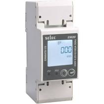 This commit does not belong to any branch on this repository, and may belong to a fork outside of the repository. unit_of_measurement: A on_turn_off: 1.2 Amps 252.8 Volts 542.4 Watts Meter 2.11 Amps By any chance do you know the new GPIO for this board? Change your Wi-Fi credentials and passwords. Whole home power monitoring with ESPHome - 6 Channels & 2 Channels. To connect SCT013 to ESP32 or NodeMCU, you can buy This unit is on ebay To connect or connect the SCT013 sensor to a D1 Mini, NodeMCU, or ESP32. If not, then simplify the WiFi setup as ESPHome has some issues with special characters and such in SSIDs and passphrases. Save my name, email, and website in this browser for the next time I comment. The logs will display Wi-Fi strength and connection status. The second integration is what Home Assistant calls its modules. Change), You are commenting using your Twitter account. It should be similar to micro fluctuations if you dont have a new load in your house. restore_mode: ALWAYS_OFF Its available for Windows, macOS, and Ubuntu. After this startup the software again and follow the instructions. Split Core Current Transformer 100A/50ma You also didnt post your config, but instead theirs. Select ESP32 for ESP32 MCU or ESP8266 if you are using a D1 Mini or NodeMCU and click next one. When I look at the outputs though This may take some time to complete. Can confirm this is still working. inverted: True First of all, thx for the tutorial, helping me to manage the calibrating process. id: energie_wasmachine_Wattage Any ideas appreciated! But why are you copying config from other people, and not the documentation? These are based on the 6 channel board with 1X gain. pin: GPIO4 As always, it can be done by USB or if we already have it previously configured by OTA. Well, this probably wont be much help but I wrote my own firmware as I build a device based around this board with an STM32 Blue Pill, ILI9225 TFT screen and W5500 Ethernet module. # https://esphome.io/components/esphome.html, # ESP8266: https://esphome.io/devices/nodemcu_esp8266.html, # ESP32: https://esphome.io/devices/nodemcu_esp32.html, # Wi-Fi configuration to which the module will connect, # https://esphome.io/components/wifi.html, # API so that Home Assistant can connect to the module, # Web server to be able to consult information with a Web browser, # https://esphome.io/components/web_server.html, # OTA component to be able to update the module without the need for cables, # Logger to record the messages sent by the device and be able to debug, # https://esphome.io/components/logger.html, # We indicate the pins where we have connected TX and RX of the device, taking into account that TX-> RX, RX-> TX must always be inverted, # stop_bits is only necessary if indicated by the log while testing the circuit, # We will use pzemac or pzem004t depending on whether we are using a PZEM-004T V3 or V1, # We indicate the pin of the board's LED to blink according to its status, # https://esphome.io/components/status_led.html, Geekering - ESP8266 NodeMCU Simple energy meter using PZEM004T, ESPHome - Peacefair PZEM-004T Energy Monitor, ESPHome - Peacefair PZEM-004T V3 Energy Monitor, Webmin: Managing a server from the browser, Your files from Windows, installing a Samba Server on Debian. (LogOut/ Config is as suggested by Pat Ive taken one apart and checked the signals and it seems correct. Other home automation software supporting MQTT can also use this integration. Whole home power monitoring and additional power circuits with ESPHome and Home Assistant. id: ${plug_name}_Wattage This and other articles complement the documentation of the GitHub repository where all the configuration of my ESP8266/ESP32 devices with ESPHome are available. go to the main dashboard and click records under Smart energy meter.
  Change). SCT-013-030 30A/1V - 9210, SCT-024TSL-B27 200A/100mA - 12597 *(2 chan board, gain_pga = 4X), For the 2 channel board and the 9VAC power supply: You can also add beautiful infographics with Micrograph card integration. To get a higher wattage use a lower number for the current_resistor. # Enable logging You can also use the SCT013 sensor rated 5A 1V, 10A 1V, 15A 1V, 20A 1V, 50A 1V or 100A 1V according to your requirements. power_id: ${plug_name}_Wattage Interesting, I havent noticed a difference. Relay: GPIO4 name: ${plug_name}_Status, switch: New buyers might want to back off until a fix is found and released. Best will be to get a different Tuya based brand! We have two methods to perform this power integration: onboard the microcontroller with ESPHome, or on the Home Assistant server. Would love to see an updated video on that. platform: ESP8266
  You can also customize the cards in your room to add a scale that shows the current demand. name: ${plug_name}_Total Daily Energy sel_pin: Bu January 7, 2022 ESP32 NodeMCU Once the firmware is compiled, click Download project. In the smart energy meter File and copy and paste This YAML code. Powered by. Looks like the docs show all the connections needed as well as the YAML config. After flashing the firmware, the ESP MCU will connect to Wi-Fi and be online in the ESPHome Dashboard. number: GPIO12 Its only for new ones that are made in the factory right now or you connect to the app. Create a network test with password test123456789, WPA2. unit_of_measurement: W This will install the ESPHome Dashboard into your home assistant. Any updates on the Tuya Convert 2.0. platform: uptime # Lower value gives lower voltage readout He uses a board from CircuitSetup plus an ESP32 with ESPHome. pin: GPIO13 If we have made the connections well and the line that we are measuring is currently consuming, we will see how the values shown change. Also enable guardAnd the auto update, And the appear in the sidebar. Although this is a written guide its meant to be used in conjunction with the video I made. According to Tasmota, The Teckin SP23 appears to be a clone of the BlitzWolf SHP2, but I dont see that listed as an option on ESPHome. ESPHome provides two parameters to mitigate wear: we could set min_save_interval to a longer duration in order to reduce the number of writes, or we could set restore to false and skip writing entirely. Add at least 10 values and then find the average. Non-invasive 30 amp 1 volt AC clamp sensor SCT013. Your email address will not be published. The third video is about using Grafana to make some nice graphs about all the data we are now collecting in Home-Assistant. I noticed an issue was already opened on the Tuya-Convert project page. name: ${plug_name}_Voltage name: ${plug_name}_Voltage inverted: True platform: gpio pin: However, the laptop will have a larger power footprint and consume more power than a Raspberry Pi 3 or a Raspberry Pi 4. current_res: 0.00221 Instructions for setting up ATM90E32 energy metering sensors. This also allows you to see the activity status of the device, i.e. ESPHome is a Home Assistant add-on that will be used to create and flash custom firmware on an ESP32, NodeMCU, or D1Mini microcontroller. In this video we are going to upload the actual config we are going to use in ESPhome, calibrate the energy meter and then make it available in Home Assistant and build a simple graph, if you want to follow along, take a look at the video and find all text fields you might need below! Madeline announces her due date after revealing the, Cowboys don't have a closed door when signing the 4-Time Pro Bowler, Thanos' son revealed the true secret of Marvel's ultimate power, Kirby and the Forgotten Lands wild mod bodes well for the future of the series, Supreme Court Reimposes Death Sentence for Boston Marathon Bomber. , Energy meters: 1.1 Amps 245.7 Volts 516 Watts Meter: 2.11Amps I flashed ESP32 with . then: Once done, you can see the actual current values. A simple way to achieve this goal is by installing energy meters per device and/or globally throughout the home. I hope you have a lock on your electric panel to keep curious hands off it!! Any smartphone charger will work with a 5V output. restore_mode: ALWAYS_ON Once the software is configured and the circuit is connected, we can plug in the transformer, we wait a few seconds and we can access the Web Server by typing the IP of the device in any Web browser.+. The former means we lose some amount of data when we reset, the latter means we lose all the data. inverted: True WARNING: This is an advanced tutorial and requires touching the electrical panel of the house, that implies certain knowledge of electricity and electronics, as well as ensuring the total cut of the current before handling. Got 16 Gosund SP-1s from Amazon.de and they all running ESPHome atm. By improving the circuit and protecting it, we can mount the energy meter that we have just built in our electrical panel and control consumption and other parameters that provide data on how our electrical installation behaves. (LogOut/ unit_of_measurement: V Which build is correct? ssid: SSID If you dont have a Raspberry Pi, you can also use your old laptop. name: ${plug_name}_Amperage We are going to follow a fairly simple scheme that can be adapted to different needs and assemblies. !There is updated code lower on this page, go and copy that instead of what is above this text! password: password Dont use someone elses. It sounds like you can get ct circuits that have built in protection? You can also build one, as I did, by following this circuit diagram. Try to connect your ESP32 to it. All ideas from anybody is more than welcome!! Follow these steps to install the ESPHome add-on in HA. Be careful while removing the extension board cable. I can confirm that this still works with the Gosund plugs currently sold on Amazon.de. Voltage works in reverse, to get a higher voltage, use a higher number in voltage_divider! Lots of how-tos have been written for that, so check one of those if you dont have this setup yet. The steps are as follows. If not, then something is up with your WiFi. I've been using RTL-SDR to read power from my meter; however, I have received notice that the meter will be changed out soon and I will likely lose easy local access to the power data feed. Hi there! power_id: energie_wasmachine_Wattage Crazy to me as well. pin: GPIO2 The rest are pre-adjustment current wrong. So make sure to watch that too, in that video I will refer to text blocks which can be found here in this article. name: ${plug_name}_Total Daily Energy I get strange upwards lines in my graph at periods of no usage. You can then use this information as events in Home Assistant to create automation, such as sending you notifications on your smartphone or via Alexa or Google Assistant. I recently ordered a Blitzwolff BW-SHP6 and was able to follow your instructions including OTA with tuya-convert. pin: on_press: Ill take a look to see if thats the case for me too. Through the interior of the ring we will have to pass the Phase cable (Black) on which we want to make the measurements, and it may or may not be the same as the one we have used to give current to the circuit. If I had to guess, if it doesnt connect to your WiFi, you would have something wrong in the WiFi section of your config. name: ${plug_name}_button First we are going to put the software generated with ESPHome to the ESP module. platform: hlw8012 Update 2019/08/24 - For v1.2 of the board your voltage calibration will be high, >64,000. I just get an error This entity does not have a unique ID. ESP8266 Mains Current Sensor - Wemos - Current transformer - SCT013 - 100A/50mA Split Single Phase Real Time Whole House Energy Meter v1.4, Expandable 6 Channel ESP32 Energy Meter Main Board, CircuitSetup/Split-Single-Phase-Energy-Meter/blob/ab6d62cceb1a1c65cf83e59deb13024d54952bda/Software/examples/HA-ESPHome_energy_meter_detailed_power.yaml, digiblur/digiNRG_ESPHome/blob/38a65c12c91337440c558cb50b25f5f440334fee/digi_nrg_2chan32.yaml. Once you have the file in place in the files directory wewe can start the flash script. Join our newsletter for free tech tips, reviews, ebooks and exclusive deals! Im not fully sure what module you have, I show the EU Gosund version. Did you make it work yet? Thanks for this post! Download home stripper tool and launch it. LED Blue: GPIO13 Pzem,
  There were some slight variations (especially the menu while flashing) but in general it worked very well. platform: status Home Assistant is open source home automation that puts local control and privacy first. (2 published articles). filters: Besides monitoring energy use by the whole home, you can build various smart energy monitoring sensors with the SCT013 or PZEM-004T sensor to effectively and accurately track energy use by individual or specific household appliances, such as heating, ventilation and air conditioning, electric heaters, and motors , heaters. Find the newly created project and click release. i am now planing to do some scripting and use RPI with custom board for 3phases There seems to be an issue with calculating the integral on those periods, as InfluxDB has no data at those moments. The fourth and last video in this series (for now) is going to be how we were able to lower our power usage because of the insight these plugs provided and some automations using Node-Red that can be configured to again, use less power and hopefully, in the end, make these plugs pay for themselves! The Total Daily Energy component accumulates value from a specified power sensor and integrates a daily tally. Does it work? This differs per Linux version, in my case Im using Ubuntu 18.10 which renames adapters. You can support me through Paypal, GitHub or simply by disabling the ad blocker. SCT-013-050 50A/1V - 15420 8 minute read. On Aliexpress, this seller is selling versions pre-flashed to Tasmota, so those can easily be used that way or flashed over to ESPhome (as I show in my guides). I cant get CircuitSetup 2 ch unit ESP 32 to join my network. cf_pin: GPIO04 Ive got one that I purchased december 2018 and never connected to the app. inverted: True Change), You are commenting using your Facebook account. Then install the SCT013 sensor on the exposed phase wire (red wire) and operate a load, such as a microwave or fan. platform: homeassistant pin: GPIO3. 8g (Without Wemos). switch.toggle: ${plug_name}_Relay (And 8 Ways to Shrink It), The xXx video game with co-op must include Vin, Survivle is a new Wordle clone with exactly the, Explanation of the second season tribute to Bridgerton, Robert Cremo III: 5 quick facts you need to know, How to activate the Great Rune of the Fetus, Final evolution of pokemon scarlet and violet may be. Does it work? document.getElementById( "ak_js_1" ).setAttribute( "value", ( new Date() ).getTime() ); TMP36 Temperature Sensor + ESP8266 = Not a GreatTeam, High-Side Fan ESP8266 PWM UsingOptocoupler, ESP8266 Controlling 4-Wire CPU CoolingFan. 5 minute read. on_turn_on: Required fields are marked *. switch.toggle: relay Remote Desktop Protocol can be hugely useful, but this technology is not airtight in terms of Amazon has a cloud service for backing up photos and videos, appropriately called Amazon Photos, but How to build a home energy monitor with ESP8266, How much power does your computer use? Save it and click fix. The CircuitSetupATM90E32Split Single Phase Energy Meter can monitor the energy usage in your entire home in real time. Its time to find out how much electricity your computer uses and how to reduce it. Check the records and replace the values. name: ${plug_name}_LED_Red Will it work? I bought 4 TP23 (via provided link) and successfully flashed them. EU Style: https://geni.us/eSgZi You can quickly access the dashboard from the sidebar and check how much energy is being used today. multiply: 0.001 Your email address will not be published. I have no updated this article for this (this method still works) but Frenck, a colleague has made an excellent article how to use this new method. We are going to need these later on! # Multiplication factor from W to kW is 0.001 This makes replacing the number in all the separate metering plugs a lot easier since you can now just change the one substitution and it will change all the parts of the code for you! For anyone checking got a pack of 4 Gosund Sp1 from amazon.de worked very easy with tuya-convert or rpi3. ESPHome, number: GPIO3 If power readings are taken at high frequency, this could wear out flash storage very quickly. Will give you more information than just sticking a current clamp on the analog input of an ESP8266, more accurate and more reliable. Or just the ones sold now. Yep. You signed in with another tab or window. cf_pin: GPIO05 Pay attention! Just to let you know that I got 4 Gosund SP-1 from Amazon.es and this tutorial is still valid. After installation, click Begins. Im looking for an idea to monitor the power consumption of my minipc with HA. 41.0mm x 32.1mm x 20mm (if Wemos D1 fitted). No updates right now, but the 2.0 method should work on plugs that have the blocked firmware! sensor: make sure what version you have https://www.esphome-devices.com/devices/BlitzWolf-BW-SHP2-Power-Monitoring-Plug/. unit_of_measurement: W Currently trying to figure out why that is. The docs should always be correct. However, the energy_XX_Total Daily Energy in the plug web interface seems to be different from the total usage in Grafana, using the integral and cumulative_sum, like you explained in your video. switch.turn_off: red_led, platform: gpio Does your Update 2019-06 Preventative measures mean I cant flash any plug with tuya convert anymore? Domotic, Besides, it also helps you conserve energy and prevent wastage. You can also split the usage into hours. Powered by a worldwide community of tinkerers and DIY enthusiasts. The calibration can be changed in the ESPhome code by varying the current_resistor and voltage_divider values. Phase and Neutral wires will be connected to direct current from the house. pin: GPIO1 power: The next step is to sum up all of these readings over time to calculate energy produced/consumed. id: red_led (Works for PC or Raspberry Pi without WiFi), PR10-C Power Meter:http://geni.us/h8kokVq. An alternative way to calibrate sensor values You can peel the outer covering from the extension board cable and expose the inner wires. digiNRG - Whole Home Power Monitoring with ESPHome, Sample Calibrations for Gain Voltage (gain_voltage), CircuitSetup 6 Channel or 2 Channel Board. change_mode_every: 8 current_resistor: ${current_res} If it does work, then add the power monitor. To measure the current and calibrate the sensor, you need to install it on the phase wire (usually red) coming from the electricity meter to your homes distribution box. SCT-013-000 100A/50ma - 3900. digi_nrg_2chan32.yaml - Included in this repo How can i set it up to the correct level? # Multiplication factor from W to kW is 0.001 unit_of_measurement: A This will download the .bin firmware file to your computer. fill(0) in the grouping should help, but doesnt for me. esphome: The button on the top works. Changing the values, i could set up the voltage, and the wattage, but the current shows almost the half of the measured one.
  Since the smart energy meter is online and connected to the Internet, you can upload the code wireless. update_interval: 10s The inspection plate is off of course and the room it is in even has a lock as well that stays locked. While I can type some commands and move around its directories, its not something Im used to or like to deal with. Ever since weve moved to our new house we have been having trouble keeping our energy usage in check. You can then replicate the code and change the CS_Pin and CT identifiers. The first integration refers to the math, called Riemann sum integral. I got the following working with one of the latest Blitzwolf BW-SPH2 ( SPC1 V2.4 on the printboard ) at home assistantgo to the Settings and click Add-ons, backup and admin. If more things go wrong or nothing seems to happen make sure to take a close look at the other log files also located in the scripts directory, they can give you valuable information what might be wrong. Do you perhaps have periods where your device uses 0 Watt? Once we have voltage and current, multiplying them gives us power at a particular instant. (It also needs the Time component to know when midnight rolls around, in order to reset to zero.) Problem with Port 53 being used already, stopping that program. Alternatively, we can perform this calculation on Home Assistant server with the unfortunately named integration integration. esphome flashed and working good. voltage: However, what I can suggest for you is to start your ESPHome configuration from scratch. If your electricity meter does not display the current value, or you cannot access the meter, follow the next method to calibrate the sensor values. I am trying to integrate the CircuitSetup 2 ch unit into HA with ESP home and cant get it to work. If your adapters are called wlan0 and eth0 you dont need to change the config.txt file since the default values are correct. unit_of_measurement: kWh, # Extra sensor to keep track of plug uptime I find it hard pressed that you got one with updated firmware, its going to take weeks if not months before those are out of the factory. Just the button is not working. Note: Some ESP modules allow 5V current output per pin, others do not. I would probably include a label or warning on my enclosure to "NEVER DISCONNECT/OPEN CT CIRCUIT BEFORE THE SPILT CORE IS OPEN.".
  After I restarted Home Assistant, a new tally started counting up on my dashboard, but I could not do anything else with the user interface element. Then replace the ones in filters The values are as described above. The danger with using someone elses config is that sometimes there are code changes which may invalidate that configuration. Wide open meter boxes with exposed terminals. In this article we are going to focus on placing a energy meter in the electrical panel to measure the consumption of our entire house. select room (Select the default room if you havent created any rooms yet) and click next one. In the video you show using the ESP8285 for the US Teckin SP20s, but on ESPHomes site they show a different board. platform: gpio Awesome vid! 2 minute read. On the upside, doing this math on the server meant data in progress will be tracked and saved in a real database, kept on a real storage device instead of fragile flash memory. mode: INPUT_PULLUP Thanks OP for a detailed write up. Check the tuya-flash github page, they have a wiki with the pinouts for lots of different models! If you are going to power the ESP module with a USB cable and feed the PZEM-004T module from its 5V/VCC and GND pins, check that these pins offer the desired current. name: ${plug_name}_Wattage inverted: True 2 minute read. voltage_divider: ${voltage_div} Lots of stuff to coverand Travis does a good job. Wondering if computers use a lot of energy? Comment document.getElementById("comment").setAttribute( "id", "ae13a12ece5cf3ffd936cae4736abd87" );document.getElementById("b61f091a2c").setAttribute( "id", "comment" ); document.getElementById( "ak_js_1" ).setAttribute( "value", ( new Date() ).getTime() ); Tuya, the manufacturer of these plugs has taken some preventative measures that make the below mentioned OTA flashing method impossible. The Tasmota website has a lot of information about this behaviour. Because then yes, they try and prevent this method! You can get this real value from your electricity meter. restore_mode: ALWAYS_ON
This commit does not belong to any branch on this repository, and may belong to a fork outside of the repository. unit_of_measurement: A on_turn_off: 1.2 Amps 252.8 Volts 542.4 Watts Meter 2.11 Amps By any chance do you know the new GPIO for this board? Change your Wi-Fi credentials and passwords. Whole home power monitoring with ESPHome - 6 Channels & 2 Channels. To connect SCT013 to ESP32 or NodeMCU, you can buy This unit is on ebay To connect or connect the SCT013 sensor to a D1 Mini, NodeMCU, or ESP32. If not, then simplify the WiFi setup as ESPHome has some issues with special characters and such in SSIDs and passphrases. Save my name, email, and website in this browser for the next time I comment. The logs will display Wi-Fi strength and connection status. The second integration is what Home Assistant calls its modules. Change), You are commenting using your Twitter account. It should be similar to micro fluctuations if you dont have a new load in your house. restore_mode: ALWAYS_OFF Its available for Windows, macOS, and Ubuntu. After this startup the software again and follow the instructions. Split Core Current Transformer 100A/50ma You also didnt post your config, but instead theirs. Select ESP32 for ESP32 MCU or ESP8266 if you are using a D1 Mini or NodeMCU and click next one. When I look at the outputs though This may take some time to complete. Can confirm this is still working. inverted: True First of all, thx for the tutorial, helping me to manage the calibrating process. id: energie_wasmachine_Wattage Any ideas appreciated! But why are you copying config from other people, and not the documentation? These are based on the 6 channel board with 1X gain. pin: GPIO4 As always, it can be done by USB or if we already have it previously configured by OTA. Well, this probably wont be much help but I wrote my own firmware as I build a device based around this board with an STM32 Blue Pill, ILI9225 TFT screen and W5500 Ethernet module. # https://esphome.io/components/esphome.html, # ESP8266: https://esphome.io/devices/nodemcu_esp8266.html, # ESP32: https://esphome.io/devices/nodemcu_esp32.html, # Wi-Fi configuration to which the module will connect, # https://esphome.io/components/wifi.html, # API so that Home Assistant can connect to the module, # Web server to be able to consult information with a Web browser, # https://esphome.io/components/web_server.html, # OTA component to be able to update the module without the need for cables, # Logger to record the messages sent by the device and be able to debug, # https://esphome.io/components/logger.html, # We indicate the pins where we have connected TX and RX of the device, taking into account that TX-> RX, RX-> TX must always be inverted, # stop_bits is only necessary if indicated by the log while testing the circuit, # We will use pzemac or pzem004t depending on whether we are using a PZEM-004T V3 or V1, # We indicate the pin of the board's LED to blink according to its status, # https://esphome.io/components/status_led.html, Geekering - ESP8266 NodeMCU Simple energy meter using PZEM004T, ESPHome - Peacefair PZEM-004T Energy Monitor, ESPHome - Peacefair PZEM-004T V3 Energy Monitor, Webmin: Managing a server from the browser, Your files from Windows, installing a Samba Server on Debian. (LogOut/ Config is as suggested by Pat Ive taken one apart and checked the signals and it seems correct. Other home automation software supporting MQTT can also use this integration. Whole home power monitoring and additional power circuits with ESPHome and Home Assistant. id: ${plug_name}_Wattage This and other articles complement the documentation of the GitHub repository where all the configuration of my ESP8266/ESP32 devices with ESPHome are available. go to the main dashboard and click records under Smart energy meter. You can also customize the cards in your room to add a scale that shows the current demand. name: ${plug_name}_Total Daily Energy sel_pin: Bu January 7, 2022 ESP32 NodeMCU Once the firmware is compiled, click Download project. In the smart energy meter File and copy and paste This YAML code. Powered by. Looks like the docs show all the connections needed as well as the YAML config. After flashing the firmware, the ESP MCU will connect to Wi-Fi and be online in the ESPHome Dashboard. number: GPIO12 Its only for new ones that are made in the factory right now or you connect to the app. Create a network test with password test123456789, WPA2. unit_of_measurement: W This will install the ESPHome Dashboard into your home assistant. Any updates on the Tuya Convert 2.0. platform: uptime # Lower value gives lower voltage readout He uses a board from CircuitSetup plus an ESP32 with ESPHome. pin: GPIO13 If we have made the connections well and the line that we are measuring is currently consuming, we will see how the values shown change. Also enable guardAnd the auto update, And the appear in the sidebar. Although this is a written guide its meant to be used in conjunction with the video I made. According to Tasmota, The Teckin SP23 appears to be a clone of the BlitzWolf SHP2, but I dont see that listed as an option on ESPHome. ESPHome provides two parameters to mitigate wear: we could set min_save_interval to a longer duration in order to reduce the number of writes, or we could set restore to false and skip writing entirely. Add at least 10 values and then find the average. Non-invasive 30 amp 1 volt AC clamp sensor SCT013. Your email address will not be published. The third video is about using Grafana to make some nice graphs about all the data we are now collecting in Home-Assistant. I noticed an issue was already opened on the Tuya-Convert project page. name: ${plug_name}_Voltage name: ${plug_name}_Voltage inverted: True platform: gpio pin: However, the laptop will have a larger power footprint and consume more power than a Raspberry Pi 3 or a Raspberry Pi 4. current_res: 0.00221 Instructions for setting up ATM90E32 energy metering sensors. This also allows you to see the activity status of the device, i.e. ESPHome is a Home Assistant add-on that will be used to create and flash custom firmware on an ESP32, NodeMCU, or D1Mini microcontroller. In this video we are going to upload the actual config we are going to use in ESPhome, calibrate the energy meter and then make it available in Home Assistant and build a simple graph, if you want to follow along, take a look at the video and find all text fields you might need below! Madeline announces her due date after revealing the, Cowboys don't have a closed door when signing the 4-Time Pro Bowler, Thanos' son revealed the true secret of Marvel's ultimate power, Kirby and the Forgotten Lands wild mod bodes well for the future of the series, Supreme Court Reimposes Death Sentence for Boston Marathon Bomber. , Energy meters: 1.1 Amps 245.7 Volts 516 Watts Meter: 2.11Amps I flashed ESP32 with . then: Once done, you can see the actual current values. A simple way to achieve this goal is by installing energy meters per device and/or globally throughout the home. I hope you have a lock on your electric panel to keep curious hands off it!! Any smartphone charger will work with a 5V output. restore_mode: ALWAYS_ON Once the software is configured and the circuit is connected, we can plug in the transformer, we wait a few seconds and we can access the Web Server by typing the IP of the device in any Web browser.+. The former means we lose some amount of data when we reset, the latter means we lose all the data. inverted: True WARNING: This is an advanced tutorial and requires touching the electrical panel of the house, that implies certain knowledge of electricity and electronics, as well as ensuring the total cut of the current before handling. Got 16 Gosund SP-1s from Amazon.de and they all running ESPHome atm. By improving the circuit and protecting it, we can mount the energy meter that we have just built in our electrical panel and control consumption and other parameters that provide data on how our electrical installation behaves. (LogOut/ unit_of_measurement: V Which build is correct? ssid: SSID If you dont have a Raspberry Pi, you can also use your old laptop. name: ${plug_name}_Amperage We are going to follow a fairly simple scheme that can be adapted to different needs and assemblies. !There is updated code lower on this page, go and copy that instead of what is above this text! password: password Dont use someone elses. It sounds like you can get ct circuits that have built in protection? You can also build one, as I did, by following this circuit diagram. Try to connect your ESP32 to it. All ideas from anybody is more than welcome!! Follow these steps to install the ESPHome add-on in HA. Be careful while removing the extension board cable. I can confirm that this still works with the Gosund plugs currently sold on Amazon.de. Voltage works in reverse, to get a higher voltage, use a higher number in voltage_divider! Lots of how-tos have been written for that, so check one of those if you dont have this setup yet. The steps are as follows. If not, then something is up with your WiFi. I've been using RTL-SDR to read power from my meter; however, I have received notice that the meter will be changed out soon and I will likely lose easy local access to the power data feed. Hi there! power_id: energie_wasmachine_Wattage Crazy to me as well. pin: GPIO2 The rest are pre-adjustment current wrong. So make sure to watch that too, in that video I will refer to text blocks which can be found here in this article. name: ${plug_name}_Total Daily Energy I get strange upwards lines in my graph at periods of no usage. You can then use this information as events in Home Assistant to create automation, such as sending you notifications on your smartphone or via Alexa or Google Assistant. I recently ordered a Blitzwolff BW-SHP6 and was able to follow your instructions including OTA with tuya-convert. pin: on_press: Ill take a look to see if thats the case for me too. Through the interior of the ring we will have to pass the Phase cable (Black) on which we want to make the measurements, and it may or may not be the same as the one we have used to give current to the circuit. If I had to guess, if it doesnt connect to your WiFi, you would have something wrong in the WiFi section of your config. name: ${plug_name}_button First we are going to put the software generated with ESPHome to the ESP module. platform: hlw8012 Update 2019/08/24 - For v1.2 of the board your voltage calibration will be high, >64,000. I just get an error This entity does not have a unique ID. ESP8266 Mains Current Sensor - Wemos - Current transformer - SCT013 - 100A/50mA Split Single Phase Real Time Whole House Energy Meter v1.4, Expandable 6 Channel ESP32 Energy Meter Main Board, CircuitSetup/Split-Single-Phase-Energy-Meter/blob/ab6d62cceb1a1c65cf83e59deb13024d54952bda/Software/examples/HA-ESPHome_energy_meter_detailed_power.yaml, digiblur/digiNRG_ESPHome/blob/38a65c12c91337440c558cb50b25f5f440334fee/digi_nrg_2chan32.yaml. Once you have the file in place in the files directory wewe can start the flash script. Join our newsletter for free tech tips, reviews, ebooks and exclusive deals! Im not fully sure what module you have, I show the EU Gosund version. Did you make it work yet? Thanks for this post! Download home stripper tool and launch it. LED Blue: GPIO13 Pzem, Since the smart energy meter is online and connected to the Internet, you can upload the code wireless. update_interval: 10s The inspection plate is off of course and the room it is in even has a lock as well that stays locked. While I can type some commands and move around its directories, its not something Im used to or like to deal with. Ever since weve moved to our new house we have been having trouble keeping our energy usage in check. You can then replicate the code and change the CS_Pin and CT identifiers. The first integration refers to the math, called Riemann sum integral. I got the following working with one of the latest Blitzwolf BW-SPH2 ( SPC1 V2.4 on the printboard ) at home assistantgo to the Settings and click Add-ons, backup and admin. If more things go wrong or nothing seems to happen make sure to take a close look at the other log files also located in the scripts directory, they can give you valuable information what might be wrong. Do you perhaps have periods where your device uses 0 Watt? Once we have voltage and current, multiplying them gives us power at a particular instant. (It also needs the Time component to know when midnight rolls around, in order to reset to zero.) Problem with Port 53 being used already, stopping that program. Alternatively, we can perform this calculation on Home Assistant server with the unfortunately named integration integration. esphome flashed and working good. voltage: However, what I can suggest for you is to start your ESPHome configuration from scratch. If your electricity meter does not display the current value, or you cannot access the meter, follow the next method to calibrate the sensor values. I am trying to integrate the CircuitSetup 2 ch unit into HA with ESP home and cant get it to work. If your adapters are called wlan0 and eth0 you dont need to change the config.txt file since the default values are correct. unit_of_measurement: kWh, # Extra sensor to keep track of plug uptime I find it hard pressed that you got one with updated firmware, its going to take weeks if not months before those are out of the factory. Just the button is not working. Note: Some ESP modules allow 5V current output per pin, others do not. I would probably include a label or warning on my enclosure to "NEVER DISCONNECT/OPEN CT CIRCUIT BEFORE THE SPILT CORE IS OPEN.". After I restarted Home Assistant, a new tally started counting up on my dashboard, but I could not do anything else with the user interface element. Then replace the ones in filters The values are as described above. The danger with using someone elses config is that sometimes there are code changes which may invalidate that configuration. Wide open meter boxes with exposed terminals. In this article we are going to focus on placing a energy meter in the electrical panel to measure the consumption of our entire house. select room (Select the default room if you havent created any rooms yet) and click next one. In the video you show using the ESP8285 for the US Teckin SP20s, but on ESPHomes site they show a different board. platform: gpio Awesome vid! 2 minute read. On the upside, doing this math on the server meant data in progress will be tracked and saved in a real database, kept on a real storage device instead of fragile flash memory. mode: INPUT_PULLUP Thanks OP for a detailed write up. Check the tuya-flash github page, they have a wiki with the pinouts for lots of different models! If you are going to power the ESP module with a USB cable and feed the PZEM-004T module from its 5V/VCC and GND pins, check that these pins offer the desired current. name: ${plug_name}_Wattage inverted: True 2 minute read. voltage_divider: ${voltage_div} Lots of stuff to coverand Travis does a good job. Wondering if computers use a lot of energy? Comment document.getElementById("comment").setAttribute( "id", "ae13a12ece5cf3ffd936cae4736abd87" );document.getElementById("b61f091a2c").setAttribute( "id", "comment" ); document.getElementById( "ak_js_1" ).setAttribute( "value", ( new Date() ).getTime() ); Tuya, the manufacturer of these plugs has taken some preventative measures that make the below mentioned OTA flashing method impossible. The Tasmota website has a lot of information about this behaviour. Because then yes, they try and prevent this method! You can get this real value from your electricity meter. restore_mode: ALWAYS_ON